Pacesetter Wiring Diagram

Brother Sewing Machine 681b Ug Small Electrical Shock On Foot

Atari Punk 8 Step Sequencer Schematic Synthesizer Diy Circuit

Yamaha Golf Cart Electrical Diagram Yamaha G1 Golf Cart Wiring

7 Way Trailer Diagram How To Check Horse Trailer Wiring With

Brother 461 761 606 607 Sewing Machine Threading Diagram With

Brother 461 761 606 607 Sewing Machine Threading Diagram With

Ac 07401080 d pacesetter oem series ac speed controls open chassis ip 00.
Pacesetter wiring diagram. For over 45 years. Yamaha wiring diagram g14a 328 kb yamaha wiring diagram g14e 202 kb yamaha wiring diagram g16a 318 kb yamaha wiring diagram g16e 205 kb yamaha wiring diagram g19e 311 kb yamaha wiring diagram g1a 174 kb yamaha wiring diagram g1a3 186 kb yamaha wiring diagram g1a5 230 kb yamaha wiring diagram g22a 311 kb. Grain trailer owner s manual this wilson trailer is designed for operation within legal highway speed limits on reasonable road surfaces for the type of service it was built to perform in accordance with the noted weight restrictions. Manual p n 07401080 rev d pdf.
Please choose your pacesaver model from the list to find the right batteries chargers wheel assemblies casters armrests and more. Yamaha wiring diagrams page. Up and down the highway and in and out of the field is just what the pacesetter is designed to do premium performance when and where you need it. Refer to basic wiring diagram in chapter 2.
A charge may still remain in the dc link capacitor with hazardous voltages even if the power has been turned off. The most preferred grain trailer in north america. Normal use means the loading unloading and transportation. 1 40760a cord power 1 2 11014a hardware kit 1 3 30644a handle back 1 4 11016a trigger kit 1 5 11018a wheel kit 2 6 61740a link arm left 1 7 11019a handle clamp kit 1 8 56201034 switch spst 1.
Qty description 1 56107130 1 pivot kit kit includes na 4 scr m6 x 30mm na 1 plate handle guide 2 56107120 1 hardware kit refer to inside front cover for kit contents 3na 1see compression handle. This file is a new version of the printed user manual that is shipped and packaged with bodine stock models 2982 2983 2984 and 2987. Diagram yamaha g5a gas wiring diagram yamaha g8e electric wiring diagra yamaha g14e electric wiring diagram yamaha g14a gas wiring diagram yamaha g16e electric wiring diagram yamaha g16a gas wiring diagram yamaha g19e electric wiring. Pacesetter 170 200 170hd 200hd 02 4 l n g m s 120vac blk blk wht grn wht base assembly wiring diagram 170 200 04 6 item ref.
Vintage golf cart parts inc. To avoid personal injury do not remove the cover of the ac drive until all display led lights on the digital keypad are off. Pacesetter 13 17 20. Performance headers direct fit catalytic converters and exhaust systems for cars and trucks both imported and domestic by pacesetter performance products.

12 Citroen C3 Electrical Wiring Diagram Wiring Diagram In 2020

Brother 461 761 606 607 Sewing Machine Threading Diagram Sewing

Diy Electronics With Images Circuit Simple Circuit Diy

How Amps Work With Images Diy Guitar Amp Amp Power Amp

Pin On Plans

Unique Wiring Diagram For Emergency Stop Button Diagram

Brother 651 Charger Sewing Machine Threading Diagram Sewing

Moen Kitchen Faucet Parts Diagram Moenkitchenfaucet7400repair

Brother Pacesetter Ult 2001 Computerized Sewing And Embroidery

Pin On Wiring Diagram
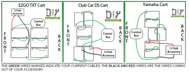
How To Wire Accessories On Your Golf Cart Accessories Locating

17 2000 Lincoln Town Car Fuel Pump Wiring Diagram Car Diagram
