P Id Block Diagram

A Proportional Integral Derivative Controller Pid Controller Is

Pid Controller Design Using Simulink Matlab Tutorial 3 With

Pid Block And Manual Pid Matlab Answers Matlab Central With

How To Read Piping And Instrumentation Diagram P Id Dengan

Parallel Pid Controller Block Diagram Pid Controller Control

Build Your Own Microcontroller Based Pid Control Line Follower

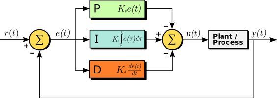
The pv is subtracted from the sp to create the error.
P id block diagram. Process instrumentation diagram p id or p i flow instrumentation diagram f id or fid block flow diagrams bfd the block flow diagram has the purpose of illustrating the logical flow of the processing phases of the product highlighting the processing sequence their concatenations and the types of treatment plant. Free online p id diagram drawing template enabled for the free online google docs. It is really very simple in operation. P id symbols and level of information available on p id may change from company to company but more or less they provide similar information.
Reading p id is a difficult task for those who start their careers in oil gas and similar chemical process industries. The distinguishing feature of the pid controller is the ability to use the three control terms of proportional integral and derivative influence on the controller output to apply. Here s a simplified block diagram of what the pid controller does. All valves and their.
P id diagram online drawing tool. Superordinate to the p id is the process flow diagram pfd which indicates the more general flow of plant processes and the relationship between major equipment of a plant facility. P id is the acronym for piping and instrumentation diagram i e. Select copy and paste the components you want to use.
I advised you before you start working on actual plant or construction project you should check the project specific symbol library which is also known as p id lead sheets or p id legend drawing. P id symbols exist for all major components and lines such as valves vessels instruments pumps compressors and towers. The error is simply multiplied by one two or all of the calculated p i and d actions depending which ones are turned on. Mechanical equipment with names and numbers.
A p id should include. R t is the desired process value or setpoint sp and y t is the measured process value pv. Each block represents a treatment unit of the process plant. Log in to your google account google accounts are free and copy file make a copy this online p id drawing template to start making your own drawings.
A block diagram of a pid controller in a feedback loop. Review of p id diagrams to draw a piping and instrumentation diagram you ll need a basic understanding of what a p id is. P id s shows all piping including physical sequences of branches reducers valves equipment instrumentation and control interlocks. You may want to review a p id symbols legend to ensure that you re using the correct shapes in an appropriate context.
The p id s are used to operate process systems. Make your own p id diagrams with this free online drawing tool. A set of standardized p id symbols is used by process engineers to draft such diagrams.

Temperature Control Using Pid Controller

Pid Controller Design Using Simulink Matlab Tutorial 3 With

Piping And Instrumentation Diagram P Id With Images Piping

A Piping And Instrumentation Diagram P Id Is A Schematic

The Pid Controller Part 1 Con Imagenes Proyectos

Pid Controller Circuit Diagram Con Imagenes Proyectos
A Proportional Integral Derivative Controller Pid Controller Is

Self Regulating Processes Liquid Flow Control With Images

Engine Control Module Block Diagram Di 2020 Dengan Gambar

The Pid Controller Part 1 In 2020

Chemical Engineering Amine Treating Unit Schematic Diagram With

What Is Pid Controller Loop Proportional Integral Derivative

Block Diagram Of Main Engine Control System Di 2020
